Call Us: +919825982091
Ultra Sonic Testing
Ultra sonic Testing
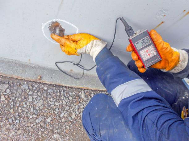
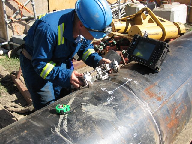
We are also very skilled in Ultrasonic inspection which is a nondestructive method in which beams of high-frequency sound waves are introduced into materials for the detection of subsurface flaws in the material. The sound waves travel through the material with some attendant loss of energy (attenuation) and are reflected at interfaces (cracks or flaws). The reflected beam is displayed and then analyzed to define the presence and location of flaws or discontinuities. A typical UT inspection system consists of several functional units, such as the pulser/receiver, transducer, and display devices. A pulser/receiver is an electronic device that can produce high voltage electrical pulses. Driven by the pulser, the transducer generates high frequency ultrasonic energy. The sound energy is introduced and propagates through the materials in the form of waves.


When there is a discontinuity (such as a crack) in the wave path, part of the energy will be reflected back from the flaw surface. The reflected wave signal is transformed into an electrical signal by the transducer and is displayed on a screen. In the applet below, the reflected signal strength is displayed versus the time from signal generation to when a echo was received. Signal travel time can be directly related to the distance that the signal traveled. From the signal, information about the reflector location, size, orientation and other features can sometimes be gained. Applications include inspections for voids, cracks, and laminations, inspections of welds and thickness measurements.
Address
3/G.F. Shreeji Complex – II,Opp.
Jankpuri Society,Nigam Socitey Road,
Ghodasar,Ahmedabad,380050
Jankpuri Society,Nigam Socitey Road,
Ghodasar,Ahmedabad,380050
We Serve Everywhere

